Mostrando las entradas con la etiqueta Arduino. Mostrar todas las entradas

viernes, 13 de julio de 2012

Arduino–Componentes para control de potencia

Estos son algunos componentes que se podrían utilizar con los proyectos de Arduino, mostrare algunos circuitos básicos para tener ideas de cómo aplicarlos.

1 – Los transistores – la imagen muestra cómo utilizarlos, el transistor debe seleccionarse según el voltaje y la corriente de operación, el especificado en la imagen es el TIP122 este transistor puede ser operado a un máximo de 100voltios y la corriente máxima de operación es de 5 amperios, recuerde que es el máximo, recomiendo utilizarlo al 70% de su capacidad, también aplicar los disipadores de calor.


Motor Transistor

image

Especificaciones del Tip122 ( Datasheet ) http://www.fairchildsemi.com/ds/TI/TIP120.pdf

2- Transistores MOSFET- Aunque luce similar al transistor, este no tiene que ver con la corriente que transcurre por su base, es solo el voltaje aplicado le Gate o compuerta de control (similar a la base del transistor), La ventaja con los mosfet es que podemos utilizar motores o cargas con mayor potencia ya que estos pueden manejar corrientes desde 10 hasta 100 amperios, estos son modelos muy comunes también encontraran de mayores capacidades pero son más costosos y no tan accesibles. mostrare algunas imágenes para sus aplicaciones sencillas.


arduino power_mosfet  image

image

3- Los Solid State Relay( Relevadores en estado sólido) – Esta alternativa lucirá mucho mas profesional si realizan un proyecto comercial o industrial, se utilizan en circuitos de corriente alterna, podrían remplazar los arrancadores magnéticos de motores, sin la necesidad de tener que remplazar contactos como en los controladores magnéticos que se utilizan en las industrias.

Pueden ser controlados con voltajes de 3 hasta 24Voltios DC, son muy versátiles, requieren disipadores de calor y si tienen ventilación será mucho mejor.


image

 image

Para motores trifasicos

image


como pueden ver hay diversas formas de contralar cargas desde Arduino. hasta la próxima.

martes, 10 de julio de 2012

Controlar 8 relays con Visual Basic y Arduino

Podrán ver como hacer que se puedan controlar 8 relays desde visual Basic 2010, tan solo con un solo botón podrás activar y desactivar. También podrán observar como los indicadores cambiaran de color verde a rojo cuando el relay este activado, Podrán comparar con la publicación anterior y podrán notar los cambios realizados en el Sketch de arduino y también en Visual Basic.
No solo podrán controlar relays, pueden apilarlo en diferentes proyectos como prender motores, lámparas, entre otras cosas. Espero les guste.

image
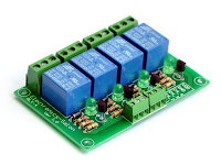
Podran utilisar diferentes paneles de relays :


Aquí les dejo el Sketch de Arduino


//apcexpert.blogspot.com
//Con este programa controlaras 8 relays con pulsar un boton para actibar y
//al pursarlo nuevamente se desactiva.

char inData[20]; // Allocate some space for the string
char inChar=-1; // Where to store the character read
byte index = 0; // Index into array; where to store the character
void setup() {
Serial.begin(9600);
pinMode(13, OUTPUT);
pinMode(12, OUTPUT);
pinMode(11, OUTPUT);
pinMode(10, OUTPUT);
pinMode(9, OUTPUT);
pinMode(8, OUTPUT);
pinMode(7, OUTPUT);
pinMode(6, OUTPUT);
}
char PinOut(char* This) {
while (Serial.available() > 0) // Don't read unless
// there you know there is data
{
if(index < 19) // One less than the size of the array
{
inChar = Serial.read(); // Read a character
inData[index] = inChar; // Store it
index++; // Increment where to write next
inData[index] = '\0'; // Null terminate the string
}
}
if (strcmp(inData,This) == 0) {
for (int i=0;i<19;i++) {
inData[i]=0;
}
index=0;
return(0);
}
else {
return(1);
}
}
void loop()
{
if (PinOut("13 on")==0) { digitalWrite(13, HIGH);}
if (PinOut("13 off")==0) {digitalWrite(13, LOW);}
if (PinOut("12 on")==0) { digitalWrite(12, HIGH);}
if (PinOut("12 off")==0) {digitalWrite(12, LOW);}
if (PinOut("11 on")==0) { digitalWrite(11, HIGH);}
if (PinOut("11 off")==0) {digitalWrite(11, LOW);}
if (PinOut("10 on")==0) { digitalWrite(10, HIGH);}
if (PinOut("10 off")==0) {digitalWrite(10, LOW);}
if (PinOut("9 on")==0) { digitalWrite(9, HIGH);}
if (PinOut("9 off")==0) {digitalWrite(9, LOW);}
if (PinOut("8 on")==0) { digitalWrite(8, HIGH);}
if (PinOut("8 off")==0) {digitalWrite(8, LOW);}
if (PinOut("7 on")==0) { digitalWrite(7, HIGH);}
if (PinOut("7 off")==0) {digitalWrite(7, LOW);}
if (PinOut("6 on")==0) { digitalWrite(6, HIGH);}
if (PinOut("6 off")==0) {digitalWrite(6, LOW);}

}


Visual Basic 2010


Imports System.IO
Imports System.IO.Ports
Imports System.Threading
Public Class Form1
    ' Shared _continue As Boolean
    ' Shared _serialPort As SerialPort
    Dim pinout13 As Boolean = True
    Dim pinout12 As Boolean = True
    Dim pin11 As Boolean = True
    Dim pinout10 As Boolean = True
    Dim pinout9 As Boolean = True
    Dim pinout8 As Boolean = True
    Dim pinout7 As Boolean = True
    Dim pinout6 As Boolean = True

    Private Sub Form1_Load(ByVal sender As System.Object, ByVal e As System.EventArgs) Handles MyBase.Load
        SerialPort1.Close()
        SerialPort1.PortName = "com4" 'Cambiar el numero de Puerto "COM"
        SerialPort1.BaudRate = 9600
        SerialPort1.DataBits = 8
        SerialPort1.Parity = Parity.None
        SerialPort1.StopBits = StopBits.One
        SerialPort1.Handshake = Handshake.None
        SerialPort1.Encoding = System.Text.Encoding.Default
    End Sub
    Private Sub Button1_Click(ByVal sender As System.Object, ByVal e As System.EventArgs) Handles Button1.Click
        SerialPort1.Open()
        If pinout13 = True Then
            SerialPort1.Write("13 on")
            RectangleShape1.BackColor = Color.Red
        Else
            SerialPort1.Write("13 off")
            RectangleShape1.BackColor = Color.Lime
        End If
        pinout13 = Not (pinout13)
        SerialPort1.Close()
    End Sub
    Private Sub Button2_Click(ByVal sender As System.Object, ByVal e As System.EventArgs) Handles Button2.Click
        SerialPort1.Open()
        If pinout12 = True Then
            SerialPort1.Write("12 on")
            RectangleShape2.BackColor = Color.Red
        Else
            SerialPort1.Write("12 off")
            RectangleShape2.BackColor = Color.Lime
        End If
        pinout12 = Not (pinout12)
        SerialPort1.Close()
    End Sub
    Private Sub RectangleShape1_Click(ByVal sender As System.Object, ByVal e As System.EventArgs) Handles RectangleShape1.Click, RectangleShape8.Click
    End Sub
    Private Sub Button3_Click(ByVal sender As System.Object, ByVal e As System.EventArgs) Handles Button3.Click
        SerialPort1.Open()
        If pin11 = True Then
            SerialPort1.Write("11 on")
            RectangleShape3.BackColor = Color.Red
        Else
            SerialPort1.Write("11 off")
            RectangleShape3.BackColor = Color.Lime
        End If
        pin11 = Not (pin11)
        SerialPort1.Close()
    End Sub
    Private Sub Button4_Click(ByVal sender As System.Object, ByVal e As System.EventArgs) Handles Button4.Click
        SerialPort1.Open()
        If pinout10 = True Then
            SerialPort1.Write("10 on")
            RectangleShape4.BackColor = Color.Red
        Else
            SerialPort1.Write("10 off")
            RectangleShape4.BackColor = Color.Lime
        End If
        pinout10 = Not (pinout10)
        SerialPort1.Close()
    End Sub
    Private Sub RectangleShape3_Click(ByVal sender As System.Object, ByVal e As System.EventArgs) Handles RectangleShape3.Click, RectangleShape6.Click
    End Sub
    Private Sub RectangleShape4_Click(ByVal sender As System.Object, ByVal e As System.EventArgs) Handles RectangleShape4.Click, RectangleShape5.Click
    End Sub
    Private Sub RectangleShape2_Click(ByVal sender As System.Object, ByVal e As System.EventArgs) Handles RectangleShape2.Click, RectangleShape7.Click
    End Sub
    Private Sub Button8_Click(ByVal sender As System.Object, ByVal e As System.EventArgs) Handles Button8.Click
        SerialPort1.Open()
        If pinout6 = True Then
            SerialPort1.Write("6 on")
            RectangleShape8.BackColor = Color.Red
        Else
            SerialPort1.Write("6 off")
            RectangleShape8.BackColor = Color.Lime
        End If
        pinout6 = Not (pinout6)
        SerialPort1.Close()
    End Sub
    Private Sub Button5_Click(ByVal sender As System.Object, ByVal e As System.EventArgs) Handles Button5.Click
        SerialPort1.Open()
        If pinout9 = True Then
            SerialPort1.Write("9 on")
            RectangleShape5.BackColor = Color.Red
        Else
            SerialPort1.Write("9 off")
            RectangleShape5.BackColor = Color.Lime
        End If
        pinout9 = Not (pinout9)
        SerialPort1.Close()
    End Sub
    Private Sub Button6_Click(ByVal sender As System.Object, ByVal e As System.EventArgs) Handles Button6.Click
        SerialPort1.Open()
        If pinout8 = True Then
            SerialPort1.Write("8 on")
            RectangleShape6.BackColor = Color.Red
        Else
            SerialPort1.Write("8 off")
            RectangleShape6.BackColor = Color.Lime
        End If
        pinout8 = Not (pinout8)
        SerialPort1.Close()
    End Sub
    Private Sub Button7_Click(ByVal sender As System.Object, ByVal e As System.EventArgs) Handles Button7.Click
        SerialPort1.Open()
        If pinout7 = True Then
            SerialPort1.Write("7 on")
            RectangleShape7.BackColor = Color.Red
        Else
            SerialPort1.Write("7 off")
            RectangleShape7.BackColor = Color.Lime
        End If
        pinout7 = Not (pinout7)
        SerialPort1.Close()
    End Sub
End Class

Hasta la proxima.


lunes, 9 de julio de 2012

Arduino y Visual Basic 2010–Controlar relay con un solo boton

En esta publicación controlaremos 4 relays utilizando un programa creado en Visual Basic 2010, mediante la comunicación del puerto USB nos conectaremos al Arduino UNO, y este a subes activara o desactivara los relay.
Lo prepare por una petición en los comentarios y aquí esta la respuesta.
Primero el ejemplo será con 4 Relays y en la próxima publicación será con 8 relays para que puedan ver los cambios realizados y sirva de ejemplo para todos. Espero les guste.

Arduino4ChRelaySinglePulse
El circuito utilizado será el mismo de la publicación anterior:


Conecciones electricas:
Pin 13 – canal 1
pin 12 – canal 2
pin 11 – canal 3
pin 10 – canal 4
 image
image

A continuación el Sketch de Arduino UNO


//apcexpert.blogspot.com
//Con este programa controlaras 4 relays con pulsar un botón para activar y
//al pulsarlo nuevamente se desactiva.

char inData[20]; // Allocate some space for the string
char inChar=-1; // Where to store the character read
byte index = 0; // Index into array; where to store the character
void setup() {
Serial.begin(9600);
pinMode(13, OUTPUT);
pinMode(12, OUTPUT);
pinMode(11, OUTPUT);
pinMode(10, OUTPUT);

}
char PinOut(char* This) {
while (Serial.available() > 0) // Don't read unless
// there you know there is data
{
if(index < 19) // One less than the size of the array
{
inChar = Serial.read(); // Read a character
inData[index] = inChar; // Store it
index++; // Increment where to write next
inData[index] = '\0'; // Null terminate the string
}
}
if (strcmp(inData,This) == 0) {
for (int i=0;i<19;i++) {
inData[i]=0;
}
index=0;
return(0);
}
else {
return(1);
}
}
void loop()
{
if (PinOut("13 on")==0) { digitalWrite(13, HIGH);}
if (PinOut("13 off")==0) {digitalWrite(13, LOW);}
if (PinOut("12 on")==0) { digitalWrite(12, HIGH);}
if (PinOut("12 off")==0) {digitalWrite(12, LOW);}
if (PinOut("11 on")==0) { digitalWrite(11, HIGH);}
if (PinOut("11 off")==0) {digitalWrite(11, LOW);}
if (PinOut("10 on")==0) { digitalWrite(10, HIGH);}
if (PinOut("10 off")==0) {digitalWrite(10, LOW);}


}


Continuamos con el codigo fuente de Visual Basic 2010


Imports System.IO
Imports System.IO.Ports
Imports System.Threading
Public Class Form1
    ' Shared _continue As Boolean
    ' Shared _serialPort As SerialPort
    Dim pinout13 As Boolean = True
    Dim pinout12 As Boolean = True
    Dim pin11 As Boolean = True
    Dim pinout10 As Boolean = True

    Private Sub Form1_Load(ByVal sender As System.Object, ByVal e As System.EventArgs) Handles MyBase.Load
        SerialPort1.Close()
        SerialPort1.PortName = "com4" 'Cambiar el numero de Puerto "COM"
        SerialPort1.BaudRate = 9600
        SerialPort1.DataBits = 8
        SerialPort1.Parity = Parity.None
        SerialPort1.StopBits = StopBits.One
        SerialPort1.Handshake = Handshake.None
        SerialPort1.Encoding = System.Text.Encoding.Default
    End Sub
    Private Sub Button1_Click(ByVal sender As System.Object, ByVal e As System.EventArgs) Handles Button1.Click
        SerialPort1.Open()
        If pinout13 = True Then
            SerialPort1.Write("13 on")
            RectangleShape1.BackColor = Color.Red
        Else
            SerialPort1.Write("13 off")
            RectangleShape1.BackColor = Color.Lime
        End If
        pinout13 = Not (pinout13)
        SerialPort1.Close()
    End Sub
    Private Sub Button2_Click(ByVal sender As System.Object, ByVal e As System.EventArgs) Handles Button2.Click
        SerialPort1.Open()
        If pinout12 = True Then
            SerialPort1.Write("12 on")
            RectangleShape2.BackColor = Color.Red
        Else
            SerialPort1.Write("12 off")
            RectangleShape2.BackColor = Color.Lime
        End If
        pinout12 = Not (pinout12)
        SerialPort1.Close()
    End Sub
    Private Sub RectangleShape1_Click(ByVal sender As System.Object, ByVal e As System.EventArgs) Handles RectangleShape1.Click
    End Sub
    Private Sub Button3_Click(ByVal sender As System.Object, ByVal e As System.EventArgs) Handles Button3.Click
        SerialPort1.Open()
        If pin11 = True Then
            SerialPort1.Write("11 on")
            RectangleShape3.BackColor = Color.Red
        Else
            SerialPort1.Write("11 off")
            RectangleShape3.BackColor = Color.Lime
        End If
        pin11 = Not (pin11)
        SerialPort1.Close()
    End Sub
    Private Sub Button4_Click(ByVal sender As System.Object, ByVal e As System.EventArgs) Handles Button4.Click
        SerialPort1.Open()
        If pinout10 = True Then
            SerialPort1.Write("10 on")
            RectangleShape4.BackColor = Color.Red
        Else
            SerialPort1.Write("10 off")
            RectangleShape4.BackColor = Color.Lime
        End If
        pinout10 = Not (pinout10)
        SerialPort1.Close()
    End Sub
    Private Sub RectangleShape3_Click(ByVal sender As System.Object, ByVal e As System.EventArgs) Handles RectangleShape3.Click
    End Sub
    Private Sub RectangleShape4_Click(ByVal sender As System.Object, ByVal e As System.EventArgs) Handles RectangleShape4.Click
    End Sub
    Private Sub RectangleShape2_Click(ByVal sender As System.Object, ByVal e As System.EventArgs) Handles RectangleShape2.Click
    End Sub
End Class


Suerte con el proyecto. Gracias


domingo, 8 de julio de 2012

Lectura de valores en el puerto analogo de arduino


En este proyecto podremos visualizar como trabaja el puerto análogo, es sencillo pero al comprenderlo podemos aplicarlo a muchas ideas como, Voltímetro, control de temperaturas para unidades de acondicionadores de aire, controladores de carga para bancos de baterías de sistemas solares o eólicos (molinos de viento), en fin son muchísimas las aplicaciones que podemos darle al Arduino utilizando los puertos análogos.

arduinoLedPotSerial

Los componentes los podemos ver en la imagen. Publicare tres Sketch para poder comprender como funciona el puerto análogo.

El primer Sketch podremos ver como al variar la posición del pot la lectura en el puerto análogo (pin 0) se reflejara en la velocidad con que el led prende y apaga. La variación será en milisegundos.


/*
Pot sketch
blink an LED at a rate set by the position of a potentiometer
*/
const int potPin = 0; // select the input pin for the potentiometer
const int ledPin = 13; // select the pin for the LED
int val = 0; // variable to store the value coming from the sensor
void setup()
{
pinMode(ledPin, OUTPUT); // declare the ledPin as an OUTPUT
}
void loop() {
val = analogRead(potPin); // read the voltage on the pot
digitalWrite(ledPin, HIGH); // turn the ledPin on
delay(val); // blink rate set by pot value (in milliseconds)
digitalWrite(ledPin, LOW); // turn the ledPin off
delay(val); // turn led off for same period as it was turned on
}


En el segundo Sketch podremos observar como Arduino interpreta la variación de voltaje en el puerto análogo (pin0) y nos la mostrara en el Serial Monitor del programa Arduino como lo podrán ver en la imagen.

Podremos notar que cuando en el pin sea 0 Voltios el serial les mostrara 0 y cuando sea 5 Voltios entonces el serial les mostrara 1023, Los valores serán entre 0 Hasta 1023.

image


/*
AnalogReadSerial
Reads an analog input on pin 0, prints the result to the serial monitor.
Attach the center pin of a potentiometer to pin A0, and the outside pins to +5V and ground.
This example code is in the public domain.
*/

// the setup routine runs once when you press reset:
void setup() {
// initialize serial communication at 9600 bits per second:
Serial.begin(9600);
}

// the loop routine runs over and over again forever:
void loop() {
// read the input on analog pin 0:
int sensorValue = analogRead(A0);
// print out the value you read:
Serial.println(sensorValue);
delay(1); // delay in between reads for stability
}


En el siguiente Sketch combinare los dos Sketch anteriores haciendo unas modificaciones al segundo para incorporarlo al primero, para que sirva de ejemplo.


/*
Pot sketch
blink an LED at a rate set by the position of a potentiometer
*/
const int potPin = 0; // select the input pin for the potentiometer
const int ledPin = 13; // select the pin for the LED
int val = 0; // variable to store the value coming from the sensor
void setup()
{
pinMode(ledPin, OUTPUT); // declare the ledPin as an OUTPUT
// initialize serial communication at 9600 bits per second:
Serial.begin(9600);

}

void loop() {
val = analogRead(potPin); // read the voltage on the pot
digitalWrite(ledPin, HIGH); // turn the ledPin on
delay(val); // blink rate set by pot value (in milliseconds)
digitalWrite(ledPin, LOW); // turn the ledPin off
delay(val); // turn led off for same period as it was turned on

// read the input on analog pin 0:
int val = analogRead(potPin);
// print out the value you read:
Serial.println(val);
delay(1); // delay in between reads for stability
}


Esta parte es importante comprenderla porque será la base para otros proyectos que mostrare, como obtener lecturas remotas, pero será mas adelante. Espero les sirva para practicar, luego mostrare como hacer el voltímetro y el control de temperatura, para la próxima.