lunes, 11 de enero de 2016

Bluetooth con Arduino y Processing

En estre proyecto estaremos utilizando :


1- ARDUINO UNO
2- BLUETOOTH
3- PROCESSING (Software)  https://processing.org

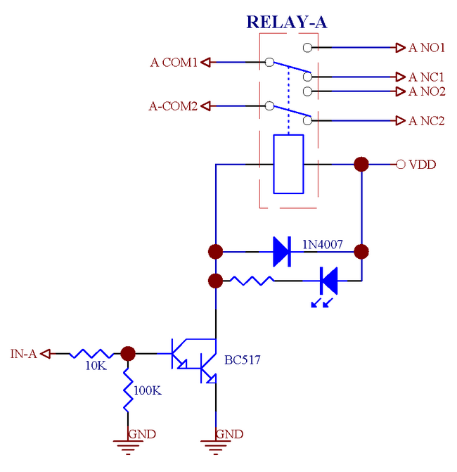
Circuito de coneccion electrica:


Arduino Sketsh:

_______________________________________________________________

char val; // variable to receive data from the serial port

int ledpin = 13; // LED connected to pin 13 (on-board LED)

void setup() {
  pinMode(ledpin, OUTPUT);  // pin 13 (on-board LED) as OUTPUT
  Serial.begin(9600);       // start serial communication at 9600bps
}

void loop() {
  if( Serial.available() )       // if data is available to read
  {
    val = Serial.read();         // read it and store it in 'val'
  }
  if( val == 'H' )               // if 'H' was received
  {
    digitalWrite(ledpin, HIGH);  // turn ON the LED
  } else { 
    digitalWrite(ledpin, LOW);   // otherwise turn it OFF
  }
  delay(100);                    // wait 100ms for next reading
}

______________________________________________________


PROCESSING

__________________________________________________


//import class to set up serial connection with wiring board
import processing.serial.*;
Serial port;
//button setup
color currentcolor;
RectButton rect1, rect2;
boolean locked = false;
void setup() {
  //set up window
  size(200, 200);
  color baseColor = color(#D8D6D6);
  currentcolor = baseColor;
  // Lista todos los puertos serie disponibles en el panel de salida.
   // Usted tendrá que elegir el puerto que la tarjeta
   // Conectado a partir de esta lista. El primer puerto en la lista es
   // Puerto # 0 y el tercer puerto en la lista es el puerto # 2. 
  println(Serial.list()); 
 // Abrir el puerto que la tarjeta Wiring está conectado a (en este caso 1
   // Que es el segundo puerto abierto en la matriz)
   // Asegúrese de abrir el puerto al mismo cableado de velocidad está utilizando (9600bps)
  port = new Serial(this, Serial.list()[2], 9600);
  // Definir y crear botón rectángulo # 1
  int x = 30;
  int y = 75;
  int size = 50;
  color buttoncolor = color(#14C949);
  color highlight = color(102, 51, 51); 
  rect1 = new RectButton(x, y, size, buttoncolor, highlight);
  // Definir y crear botón rectángulo # 2
  x = 120;
  y = 75; 
  size = 50;
  buttoncolor = color(#FF030B);
  highlight = color(102, 102, 102); 
  rect2 = new RectButton(x, y, size, buttoncolor, highlight);
}
void draw() {
  background(currentcolor);
  stroke(255);
  update(mouseX, mouseY);
  rect1.display();
  rect2.display();
}
void update(int x, int y) {
  if(locked == false) {
    rect1.update();
    rect2.update();
  } else {
    locked = false;
  }
  // LED encendido y apagado si los botones presionados donde
   // H = en (alta) y L = apagado (bajo)
  if(mousePressed) {
    if(rect1.pressed()) {            //ON button
      currentcolor = rect1.basecolor;
      port.write('H');
    } else if(rect2.pressed()) {    //OFF button
      currentcolor = rect2.basecolor;
      port.write('L');
    }
  }
}
class Button {
  int x, y;
  int size;
  color basecolor, highlightcolor;
  color currentcolor;
  boolean over = false;
  boolean pressed = false;   
  void update() 
  {
    if(over()) {
      currentcolor = highlightcolor;
    } else {
      currentcolor = basecolor;
    }
  }
  boolean pressed() 
  {
    if(over) {
      locked = true;
      return true;
    } else {
      locked = false;
      return false;
    }    
  }
  boolean over() 
  { 
    return true; 
  }
  void display() 
  { 
  }
}
class RectButton extends Button {
  RectButton(int ix, int iy, int isize, color icolor, color ihighlight) 
  {
    x = ix;
    y = iy;
    size = isize;
    basecolor = icolor;
    highlightcolor = ihighlight;
    currentcolor = basecolor;
  }
  boolean over() 
  {
    if( overRect(x, y, size, size) ) {
      over = true;
      return true;
    } else {
      over = false;
      return false;
    }
  }
  void display() 
  {
    stroke(255);
    fill(currentcolor);
    rect(x, y, size, size);
  }
}
boolean overRect(int x, int y, int width, int height) {
  if (mouseX >= x && mouseX <= x+width && 
      mouseY >= y && mouseY <= y+height) {
    return true;
  } else {
    return false;
  }
}

________________________________________________________

Informacion Relacionada:      http://playground.arduino.cc/Learning/Tutorial01

Hasta la proxima.


domingo, 3 de enero de 2016

Arduino ADXL335 - acelerómetro analógico

ADXL335


 Acelerómetro - un dispositivo para medir la aceleración. Es un acelerómetro de tres ejes analógicos.

Lo mejor de todos los efectos de las lecturas del sensor de aceleración estática se muestran en la especificación del sensor. En esta imagen se encuentra el secreto principal de la aceleración estática.


En primer lugar vamos a tratar con la parte derecha de la imagen, que cambia su valor Zout. De acuerdo con esta imagen, si ponemos nuestros contactos del sensor hacia abajo, el valor del eje Z es igual a uno (o más precisamente, uno g). Como ya he dicho - este valor no es más que una proyección de aceleración estática sobre el eje de nuestro sensor. Dado que en este caso el vector coincide con el eje Z, y la aceleración de la gravedad g es igual, tenemos un valor Zout = 1g. 
Si invertimos los contactos del sensor hacia arriba, el valor Zout se invierte. 
Vale la pena señalar que todo el resto de la aceleración igual a cero, esto es debido a la coincidencia vector ya se ha mencionado aceleración estática con el eje Z, y también el estado de reposo de todos los sensores. 

También es importante entender que la longitud del vector en el resto del sensor siempre será igual a la unidad. Vector no siempre coincide con ninguno de los ejes - en lugar de la opción de una excepción a la regla. En la mayoría de los casos, el vector se distribuirá en los tres ejes simultáneamente.

ADXL335 - Sensor triaxial. De hecho, esto tres acelerómetros diferentes en un solo paquete, cada uno de los cuales es responsable de su propio eje X, Y o Z. misma 


------------------------------------------------------------------------------------------------------------------------------------------

--------------------------------------------------------------------------------------------------------------------------------------------------


Arduino Sketsh
------------------------------------------------------------------------------------------------------------

/*
Arduino ADXL335 - acelerómetro analógico

 Conecciones para el circuito:

 analog pin 0: ground (tierra)
 analog pin 1: z-axis
 analog pin 2: y-axis
 analog pin 3: x-axis
 analog pin 4: voltage


// Se utilizaran los pines analogos 0=14 y 4=18 como fuente de energia.

const int voltagepin = 18;              // analogo pin 4 -- voltage
const int groundpin = 14;             // analogo pin 0 -- ground (tierra)

// La lectura pa tendremos en los pines 1,2,3 en modo analogo.

const int x-pin = A3;                  // x-axis
const int y-pin = A2;                  // y-axis
const int z-pin = A1;                  // z-axis


void setup() {
  // inicializar la comunicacion serial.
  Serial.begin(9600);

  // Recuerde que el voltage de salida es de 5 voltios.
  pinMode(voltagepin, OUTPUT);
  pinMode(powerpin, OUTPUT);
  digitalWrite(voltagepin, LOW);
  digitalWrite(powerpin, HIGH);
}

void loop() {
  // imprime el valor del sensor X:
  Serial.print(analogRead(x-pin));
  
  // imprime el valor del sensor Y:
  Serial.print("\t");
  Serial.print(analogRead(y-pin));
  
  // imprime el valor del sensor Z:
  Serial.print("\t");  
  Serial.print(analogRead(z-pin));
  Serial.println();
  
  // tiempo de espera antes de la proxima lectura:
  delay(100);
}

--------------------------------------------------------------------------------------------------------------------------------------------------------


Bueno los dejo con este simple proyecto para practica o para probar el sensor ADXL335. 
Gracias por visitar el blog.

.

lunes, 21 de enero de 2013

Prosecessing–Programa para crear aplicaciones para Arduino utilizando el puerto USB.

Nota: Para el que aun no conoce este programa.
Les presento este programa que para mí es bastante nuevo, pero lo encontré interesante porque se pueden hacer aplicaciones que corran en diferentes sistemas operativos tales como:
Windows
Linux
Mac
Android
Esto lo hace interesante ya que con Visual Basic 2010 solo podrán crear aplicaciones para Windows, aunque las podrían correr en linux utilizando una aplicación que se llama WINE.
Además está acompañado con una lista de ejemplos que podrían utilizar para un rápido aprendizaje, espero les guste ya que la programación es similar a la de los Arduino, de modo que no tendrán que complicarse mucho la vida
.
image
No sé si ellos tienen una página en español pero no esta demás aprender ingles, les recomiendo que lo intenten los que no dominen el idioma ya que hay muchas herramientas de traducción como, Google Translator, es una de ellas. (http://translate.google.com.pr/?hl=es-419&tab=wT)

La dirección para la página Oficial de Processing (http://processing.org/)
Para bajar el programa (http://processing.org/download/)
Para poder aprender (http://processing.org/learning/)
Espero les guste,
En próximas publicaciones estaremos utilizando este programa comunicándonos con Arduino.

miércoles, 16 de enero de 2013

Fritzing–Disena circuitos para Arduino

Les presento este programa para el que aun no lo conoce, es muy útil para el desarrollo de ideas para implementarlas con Arduino,, es muy interesante y espero les ayude con sus proyectos.
image
Podras crear circuitos como este:
image
Dispone de una galería de componentes que podrás utilizar:
image

Sobre Fritzing

Fritzing es una iniciativa de hardware de código abierto para apoyar a diseñadores, artistas, investigadores y aficionados a trabajar creativamente con la electrónica interactiva. Tutorial Fritzing basico en 12 minutos ESPAÑOL .
  .
 

Descarga y comienza!

http://fritzing.org/home/


miércoles, 8 de agosto de 2012

Utilice su PC como osciloscopio gratis.


Un osciloscopio es un instrumento de laboratorio utilizado para mostrar y analizar la forma de onda de las señales electrónicas. Aquí es un procedimiento sencillo, cómo hacer tu propio Osciloscopio para tu PC .

Un osciloscopio real es muy costosa y grande en tamaño, por lo que resulta poco accesible para los aficionados. Podemos utilizar esta alternativa un osciloscopio Virtua para PC .


Encontraras dos modelos que podras utilizar:


image


Descargar osciloscopio 2,51

image

Descargar Digital Osciloscopio


Cómo utilizar el osciloscopio

1) Descargue la aplicación y ejecutarlo.

El osciloscopio utiliza la tarjeta de sonido de su computadora (entrada MIC) para detectar señal, así que para proteger su tarjeta de sonido debemos hacer un pequeño circuito de interfaz mediante resistencias. (como se muestra en la figura a continuación)

image

Utilice cable coaxial para la medición de alta frecuencia, para evitar el ruido

Lista de materiales:-

1) 1 x Cable de Audio de 3.5 a 3.5 macho

2) Resistencias como se muestra en la figura

3) Sondas (puede utilizar sondas de cable multímetro)

4) Coaxial Cable para evitar ruidos durante la medición de señales de alta frecuencia.

Finalmente, tenemos un osciloscopio muy economico para las proyectos.

sábado, 28 de julio de 2012

Arduino LCD indicador de temperatura con LM35

Lector de temperaturas en grados Fahrenheit y centígrados, con display LCD, es un aplicación bastante simple e interesante.

Verdaderamente la plataforma Arduino es muy versátil, y además fácil de comprender. Durante muchos años estuve interesado en los microprocesadores y micro controladores, 8085, Pic, Paralax, Basic Stamp, AVR y otros pero los encontraba muy monótonos, pero cuando me tope con Arduino, me sorprendí, las aplicaciones que se le pueden dar son inmensas y los componentes que se pueden encontrar para esta plataforma, son súper interesantes, los GPS permiten la creación de equipos de vuelo parcialmente autónomos, con tan solo indicar las coordenadas, es un proyecto que más tarde mostrare, con los quadcopter..
También la robótica esta increíble con los Hexápodos, este será otro proyecto que mostrare más adelante, y las aplicaciones en CNC (Fresadoras), en fin son temas que mas adelante tocaremos.

Indicador de temperatura LCD
DSCF1611

image
Aqui tienen el sketch para arduino

/*
  Temperature Indicator F/C with LM35 sensor.
 
  apcexpert.blogspot.com 
 
  apcexpert.wordpress.com
*/
// LCD library code:
#include <LiquidCrystal.h>
// The numbers of the interface pins
LiquidCrystal lcd(8, 9, 4, 5, 6, 7);
// Variables
float TempC;
float TempF;
int TempPin = 1;
void setup(){
  // LCD's line position of columns and rows:
  lcd.begin(16, 2);
  lcd.print(" Temp Indicator");
  lcd.setCursor(0, 1);
  lcd.print("Temp");
}
void loop(){
  TempC = analogRead(TempPin);           //read the value from the sensor
  TempC = (5.0 * TempC * 100.0)/1024.0;  //convertion the analog data to temperature
  TempF = ((TempC*9)/5) + 32;            //convertion celcius to farenheit
  // print result to lcd display
  lcd.setCursor(11, 1);
  lcd.print(TempC,1);
  lcd.print("C");
  lcd.setCursor(5, 1);
  lcd.print(TempF,1);
  lcd.print("F");
 
  delay(1000);
}

Hasta la proxima.

Arduino IR Remote Control - Controlar 4 relays con un control remoto Infrerojo

Hoy les traigo un proyecto de como controlar un panel de 4 relays utilizando in control remoto infrarojo ( IR remote control ). se requiere tener la libreria del sensor infrerojo. Nota importante en esta libreria requiere una pequeña modificacion, solo cuando utilizas las verciones nuevas del programa de Arduino 1.0 y 1.0.1 en las anteriores no tendras problemas.

La modificacion consiste en remplazar #include <WProgram.h>
por #include <Arduino.h> en el archivo IRRemoteInt.h.

Si tienen algun problema me abisan, con gusto los ayudare.


Enlace: IR Reomote library


Conecciones electricas:
Pin 13 – canal 1
pin 12 – canal 2
pin 11 – canal 3
pin 10 – canal 4

pin 7 – señal del sensor infrarojo

image

Estoy utilizando el Control remoto modelo YK-001, lo pueden conseguir en ebay.com, en la imagen podrán ver los códigos de cada tecla, los necesitaran para su proyecto.

IR CONTROL YK-001 codes

Con el siguiente sketch de Arduino podrán localizar los códigos de otros controles, los códigos los podrán ver en el serial monitor, por si desean utilizar otro diferente:


//apcexpert.blogspot.com
// IR Remote Control Code Finder
#include <IRremote.h>
int RECV_PIN = 7; //define input pin on Arduino
IRrecv irrecv(RECV_PIN);
decode_results results;
void setup()
{
Serial.begin(9600);
irrecv.enableIRIn(); // Start the receiver
}
void loop() {
if (irrecv.decode(&results)) {
  Serial.println(results.value );
  irrecv.resume(); // Receive the next value
}
}


IR Sensor

Para finalizar, el Sketch de Arduino con el cual podremos controlar los cuatro relay como se ve en la imagen superior;


// apcexpert.blogspot.com

#include <IRremote.h>

int RECV_PIN = 7;

int Relay1_PIN = 13;
int Relay2_PIN = 12;
int Relay3_PIN = 11;
int Relay4_PIN = 10;

IRrecv irrecv(RECV_PIN);
decode_results results;

void setup()
{
  pinMode(Relay1_PIN, OUTPUT);
  pinMode(Relay2_PIN, OUTPUT);
  pinMode(Relay3_PIN, OUTPUT);
  pinMode(Relay4_PIN, OUTPUT);
 
  pinMode(6, OUTPUT);
  irrecv.enableIRIn(); // Start the receiver
}

int on = 1;


void loop() {
  if (irrecv.decode(&results)) {
    if (results.value == 16724175) { // YK-001 button 1
       {
        on = !on;
        digitalWrite(Relay1_PIN, on ? HIGH : LOW);
      }
     }
{
    if (results.value == 16718055) { // YK-001 button 2
     
       {
        on = !on;
        digitalWrite(Relay2_PIN, on ? HIGH : LOW);
      }
      }   
  {
    if (results.value == 16743045) { // YK-001 button 3
     {
        on = !on;
        digitalWrite(Relay3_PIN, on ? HIGH : LOW);
      }
     }   
  {
    if (results.value == 16716015) { // YK-001 button
     {
        on = !on;
        digitalWrite(Relay4_PIN, on ? HIGH : LOW);
      }
     }     
    irrecv.resume(); // Receive the next value
  }
}}}}


Espero que no tengan problemas, pero de tenerlos pueden comunicarse y con gusto los ayudare en lo posible. Hasta la próxima.

viernes, 13 de julio de 2012

Arduino–Componentes para control de potencia

Estos son algunos componentes que se podrían utilizar con los proyectos de Arduino, mostrare algunos circuitos básicos para tener ideas de cómo aplicarlos.

1 – Los transistores – la imagen muestra cómo utilizarlos, el transistor debe seleccionarse según el voltaje y la corriente de operación, el especificado en la imagen es el TIP122 este transistor puede ser operado a un máximo de 100voltios y la corriente máxima de operación es de 5 amperios, recuerde que es el máximo, recomiendo utilizarlo al 70% de su capacidad, también aplicar los disipadores de calor.


Motor Transistor

image

Especificaciones del Tip122 ( Datasheet ) http://www.fairchildsemi.com/ds/TI/TIP120.pdf

2- Transistores MOSFET- Aunque luce similar al transistor, este no tiene que ver con la corriente que transcurre por su base, es solo el voltaje aplicado le Gate o compuerta de control (similar a la base del transistor), La ventaja con los mosfet es que podemos utilizar motores o cargas con mayor potencia ya que estos pueden manejar corrientes desde 10 hasta 100 amperios, estos son modelos muy comunes también encontraran de mayores capacidades pero son más costosos y no tan accesibles. mostrare algunas imágenes para sus aplicaciones sencillas.


arduino power_mosfet  image

image

3- Los Solid State Relay( Relevadores en estado sólido) – Esta alternativa lucirá mucho mas profesional si realizan un proyecto comercial o industrial, se utilizan en circuitos de corriente alterna, podrían remplazar los arrancadores magnéticos de motores, sin la necesidad de tener que remplazar contactos como en los controladores magnéticos que se utilizan en las industrias.

Pueden ser controlados con voltajes de 3 hasta 24Voltios DC, son muy versátiles, requieren disipadores de calor y si tienen ventilación será mucho mejor.


image

 image

Para motores trifasicos

image


como pueden ver hay diversas formas de contralar cargas desde Arduino. hasta la próxima.

martes, 10 de julio de 2012

Controlar 8 relays con Visual Basic y Arduino

Podrán ver como hacer que se puedan controlar 8 relays desde visual Basic 2010, tan solo con un solo botón podrás activar y desactivar. También podrán observar como los indicadores cambiaran de color verde a rojo cuando el relay este activado, Podrán comparar con la publicación anterior y podrán notar los cambios realizados en el Sketch de arduino y también en Visual Basic.
No solo podrán controlar relays, pueden apilarlo en diferentes proyectos como prender motores, lámparas, entre otras cosas. Espero les guste.

image
Podran utilisar diferentes paneles de relays :


Aquí les dejo el Sketch de Arduino


//apcexpert.blogspot.com
//Con este programa controlaras 8 relays con pulsar un boton para actibar y
//al pursarlo nuevamente se desactiva.

char inData[20]; // Allocate some space for the string
char inChar=-1; // Where to store the character read
byte index = 0; // Index into array; where to store the character
void setup() {
Serial.begin(9600);
pinMode(13, OUTPUT);
pinMode(12, OUTPUT);
pinMode(11, OUTPUT);
pinMode(10, OUTPUT);
pinMode(9, OUTPUT);
pinMode(8, OUTPUT);
pinMode(7, OUTPUT);
pinMode(6, OUTPUT);
}
char PinOut(char* This) {
while (Serial.available() > 0) // Don't read unless
// there you know there is data
{
if(index < 19) // One less than the size of the array
{
inChar = Serial.read(); // Read a character
inData[index] = inChar; // Store it
index++; // Increment where to write next
inData[index] = '\0'; // Null terminate the string
}
}
if (strcmp(inData,This) == 0) {
for (int i=0;i<19;i++) {
inData[i]=0;
}
index=0;
return(0);
}
else {
return(1);
}
}
void loop()
{
if (PinOut("13 on")==0) { digitalWrite(13, HIGH);}
if (PinOut("13 off")==0) {digitalWrite(13, LOW);}
if (PinOut("12 on")==0) { digitalWrite(12, HIGH);}
if (PinOut("12 off")==0) {digitalWrite(12, LOW);}
if (PinOut("11 on")==0) { digitalWrite(11, HIGH);}
if (PinOut("11 off")==0) {digitalWrite(11, LOW);}
if (PinOut("10 on")==0) { digitalWrite(10, HIGH);}
if (PinOut("10 off")==0) {digitalWrite(10, LOW);}
if (PinOut("9 on")==0) { digitalWrite(9, HIGH);}
if (PinOut("9 off")==0) {digitalWrite(9, LOW);}
if (PinOut("8 on")==0) { digitalWrite(8, HIGH);}
if (PinOut("8 off")==0) {digitalWrite(8, LOW);}
if (PinOut("7 on")==0) { digitalWrite(7, HIGH);}
if (PinOut("7 off")==0) {digitalWrite(7, LOW);}
if (PinOut("6 on")==0) { digitalWrite(6, HIGH);}
if (PinOut("6 off")==0) {digitalWrite(6, LOW);}

}


Visual Basic 2010


Imports System.IO
Imports System.IO.Ports
Imports System.Threading
Public Class Form1
    ' Shared _continue As Boolean
    ' Shared _serialPort As SerialPort
    Dim pinout13 As Boolean = True
    Dim pinout12 As Boolean = True
    Dim pin11 As Boolean = True
    Dim pinout10 As Boolean = True
    Dim pinout9 As Boolean = True
    Dim pinout8 As Boolean = True
    Dim pinout7 As Boolean = True
    Dim pinout6 As Boolean = True

    Private Sub Form1_Load(ByVal sender As System.Object, ByVal e As System.EventArgs) Handles MyBase.Load
        SerialPort1.Close()
        SerialPort1.PortName = "com4" 'Cambiar el numero de Puerto "COM"
        SerialPort1.BaudRate = 9600
        SerialPort1.DataBits = 8
        SerialPort1.Parity = Parity.None
        SerialPort1.StopBits = StopBits.One
        SerialPort1.Handshake = Handshake.None
        SerialPort1.Encoding = System.Text.Encoding.Default
    End Sub
    Private Sub Button1_Click(ByVal sender As System.Object, ByVal e As System.EventArgs) Handles Button1.Click
        SerialPort1.Open()
        If pinout13 = True Then
            SerialPort1.Write("13 on")
            RectangleShape1.BackColor = Color.Red
        Else
            SerialPort1.Write("13 off")
            RectangleShape1.BackColor = Color.Lime
        End If
        pinout13 = Not (pinout13)
        SerialPort1.Close()
    End Sub
    Private Sub Button2_Click(ByVal sender As System.Object, ByVal e As System.EventArgs) Handles Button2.Click
        SerialPort1.Open()
        If pinout12 = True Then
            SerialPort1.Write("12 on")
            RectangleShape2.BackColor = Color.Red
        Else
            SerialPort1.Write("12 off")
            RectangleShape2.BackColor = Color.Lime
        End If
        pinout12 = Not (pinout12)
        SerialPort1.Close()
    End Sub
    Private Sub RectangleShape1_Click(ByVal sender As System.Object, ByVal e As System.EventArgs) Handles RectangleShape1.Click, RectangleShape8.Click
    End Sub
    Private Sub Button3_Click(ByVal sender As System.Object, ByVal e As System.EventArgs) Handles Button3.Click
        SerialPort1.Open()
        If pin11 = True Then
            SerialPort1.Write("11 on")
            RectangleShape3.BackColor = Color.Red
        Else
            SerialPort1.Write("11 off")
            RectangleShape3.BackColor = Color.Lime
        End If
        pin11 = Not (pin11)
        SerialPort1.Close()
    End Sub
    Private Sub Button4_Click(ByVal sender As System.Object, ByVal e As System.EventArgs) Handles Button4.Click
        SerialPort1.Open()
        If pinout10 = True Then
            SerialPort1.Write("10 on")
            RectangleShape4.BackColor = Color.Red
        Else
            SerialPort1.Write("10 off")
            RectangleShape4.BackColor = Color.Lime
        End If
        pinout10 = Not (pinout10)
        SerialPort1.Close()
    End Sub
    Private Sub RectangleShape3_Click(ByVal sender As System.Object, ByVal e As System.EventArgs) Handles RectangleShape3.Click, RectangleShape6.Click
    End Sub
    Private Sub RectangleShape4_Click(ByVal sender As System.Object, ByVal e As System.EventArgs) Handles RectangleShape4.Click, RectangleShape5.Click
    End Sub
    Private Sub RectangleShape2_Click(ByVal sender As System.Object, ByVal e As System.EventArgs) Handles RectangleShape2.Click, RectangleShape7.Click
    End Sub
    Private Sub Button8_Click(ByVal sender As System.Object, ByVal e As System.EventArgs) Handles Button8.Click
        SerialPort1.Open()
        If pinout6 = True Then
            SerialPort1.Write("6 on")
            RectangleShape8.BackColor = Color.Red
        Else
            SerialPort1.Write("6 off")
            RectangleShape8.BackColor = Color.Lime
        End If
        pinout6 = Not (pinout6)
        SerialPort1.Close()
    End Sub
    Private Sub Button5_Click(ByVal sender As System.Object, ByVal e As System.EventArgs) Handles Button5.Click
        SerialPort1.Open()
        If pinout9 = True Then
            SerialPort1.Write("9 on")
            RectangleShape5.BackColor = Color.Red
        Else
            SerialPort1.Write("9 off")
            RectangleShape5.BackColor = Color.Lime
        End If
        pinout9 = Not (pinout9)
        SerialPort1.Close()
    End Sub
    Private Sub Button6_Click(ByVal sender As System.Object, ByVal e As System.EventArgs) Handles Button6.Click
        SerialPort1.Open()
        If pinout8 = True Then
            SerialPort1.Write("8 on")
            RectangleShape6.BackColor = Color.Red
        Else
            SerialPort1.Write("8 off")
            RectangleShape6.BackColor = Color.Lime
        End If
        pinout8 = Not (pinout8)
        SerialPort1.Close()
    End Sub
    Private Sub Button7_Click(ByVal sender As System.Object, ByVal e As System.EventArgs) Handles Button7.Click
        SerialPort1.Open()
        If pinout7 = True Then
            SerialPort1.Write("7 on")
            RectangleShape7.BackColor = Color.Red
        Else
            SerialPort1.Write("7 off")
            RectangleShape7.BackColor = Color.Lime
        End If
        pinout7 = Not (pinout7)
        SerialPort1.Close()
    End Sub
End Class

Hasta la proxima.


lunes, 9 de julio de 2012

Arduino y Visual Basic 2010–Controlar relay con un solo boton

En esta publicación controlaremos 4 relays utilizando un programa creado en Visual Basic 2010, mediante la comunicación del puerto USB nos conectaremos al Arduino UNO, y este a subes activara o desactivara los relay.
Lo prepare por una petición en los comentarios y aquí esta la respuesta.
Primero el ejemplo será con 4 Relays y en la próxima publicación será con 8 relays para que puedan ver los cambios realizados y sirva de ejemplo para todos. Espero les guste.

Arduino4ChRelaySinglePulse
El circuito utilizado será el mismo de la publicación anterior:


Conecciones electricas:
Pin 13 – canal 1
pin 12 – canal 2
pin 11 – canal 3
pin 10 – canal 4
 image
image

A continuación el Sketch de Arduino UNO


//apcexpert.blogspot.com
//Con este programa controlaras 4 relays con pulsar un botón para activar y
//al pulsarlo nuevamente se desactiva.

char inData[20]; // Allocate some space for the string
char inChar=-1; // Where to store the character read
byte index = 0; // Index into array; where to store the character
void setup() {
Serial.begin(9600);
pinMode(13, OUTPUT);
pinMode(12, OUTPUT);
pinMode(11, OUTPUT);
pinMode(10, OUTPUT);

}
char PinOut(char* This) {
while (Serial.available() > 0) // Don't read unless
// there you know there is data
{
if(index < 19) // One less than the size of the array
{
inChar = Serial.read(); // Read a character
inData[index] = inChar; // Store it
index++; // Increment where to write next
inData[index] = '\0'; // Null terminate the string
}
}
if (strcmp(inData,This) == 0) {
for (int i=0;i<19;i++) {
inData[i]=0;
}
index=0;
return(0);
}
else {
return(1);
}
}
void loop()
{
if (PinOut("13 on")==0) { digitalWrite(13, HIGH);}
if (PinOut("13 off")==0) {digitalWrite(13, LOW);}
if (PinOut("12 on")==0) { digitalWrite(12, HIGH);}
if (PinOut("12 off")==0) {digitalWrite(12, LOW);}
if (PinOut("11 on")==0) { digitalWrite(11, HIGH);}
if (PinOut("11 off")==0) {digitalWrite(11, LOW);}
if (PinOut("10 on")==0) { digitalWrite(10, HIGH);}
if (PinOut("10 off")==0) {digitalWrite(10, LOW);}


}


Continuamos con el codigo fuente de Visual Basic 2010


Imports System.IO
Imports System.IO.Ports
Imports System.Threading
Public Class Form1
    ' Shared _continue As Boolean
    ' Shared _serialPort As SerialPort
    Dim pinout13 As Boolean = True
    Dim pinout12 As Boolean = True
    Dim pin11 As Boolean = True
    Dim pinout10 As Boolean = True

    Private Sub Form1_Load(ByVal sender As System.Object, ByVal e As System.EventArgs) Handles MyBase.Load
        SerialPort1.Close()
        SerialPort1.PortName = "com4" 'Cambiar el numero de Puerto "COM"
        SerialPort1.BaudRate = 9600
        SerialPort1.DataBits = 8
        SerialPort1.Parity = Parity.None
        SerialPort1.StopBits = StopBits.One
        SerialPort1.Handshake = Handshake.None
        SerialPort1.Encoding = System.Text.Encoding.Default
    End Sub
    Private Sub Button1_Click(ByVal sender As System.Object, ByVal e As System.EventArgs) Handles Button1.Click
        SerialPort1.Open()
        If pinout13 = True Then
            SerialPort1.Write("13 on")
            RectangleShape1.BackColor = Color.Red
        Else
            SerialPort1.Write("13 off")
            RectangleShape1.BackColor = Color.Lime
        End If
        pinout13 = Not (pinout13)
        SerialPort1.Close()
    End Sub
    Private Sub Button2_Click(ByVal sender As System.Object, ByVal e As System.EventArgs) Handles Button2.Click
        SerialPort1.Open()
        If pinout12 = True Then
            SerialPort1.Write("12 on")
            RectangleShape2.BackColor = Color.Red
        Else
            SerialPort1.Write("12 off")
            RectangleShape2.BackColor = Color.Lime
        End If
        pinout12 = Not (pinout12)
        SerialPort1.Close()
    End Sub
    Private Sub RectangleShape1_Click(ByVal sender As System.Object, ByVal e As System.EventArgs) Handles RectangleShape1.Click
    End Sub
    Private Sub Button3_Click(ByVal sender As System.Object, ByVal e As System.EventArgs) Handles Button3.Click
        SerialPort1.Open()
        If pin11 = True Then
            SerialPort1.Write("11 on")
            RectangleShape3.BackColor = Color.Red
        Else
            SerialPort1.Write("11 off")
            RectangleShape3.BackColor = Color.Lime
        End If
        pin11 = Not (pin11)
        SerialPort1.Close()
    End Sub
    Private Sub Button4_Click(ByVal sender As System.Object, ByVal e As System.EventArgs) Handles Button4.Click
        SerialPort1.Open()
        If pinout10 = True Then
            SerialPort1.Write("10 on")
            RectangleShape4.BackColor = Color.Red
        Else
            SerialPort1.Write("10 off")
            RectangleShape4.BackColor = Color.Lime
        End If
        pinout10 = Not (pinout10)
        SerialPort1.Close()
    End Sub
    Private Sub RectangleShape3_Click(ByVal sender As System.Object, ByVal e As System.EventArgs) Handles RectangleShape3.Click
    End Sub
    Private Sub RectangleShape4_Click(ByVal sender As System.Object, ByVal e As System.EventArgs) Handles RectangleShape4.Click
    End Sub
    Private Sub RectangleShape2_Click(ByVal sender As System.Object, ByVal e As System.EventArgs) Handles RectangleShape2.Click
    End Sub
End Class


Suerte con el proyecto. Gracias


domingo, 8 de julio de 2012

Visual Basic 2010 y Arduino – Servo control con LCD display.


En el post anterior presente como controlar un servo utilizando un Slider en Visual BASIC 2010, ahora les traigo una actualización para mejorar su apariencia y añadir nuevas funciones. Espero les guste, para que les funcione idéntico tienen que instalar un tipo de letra digital si no la tienen los dígitos no lucirán iguales, lo encontraran en el mismo sitio que este archivo. ( 11569_DIGITAL.ttf )


Enlace a la publicación anterior:
Arduino – Visual Basic 2010 Servo control con LCD display
 
Arduino Sketch
_______________________________________________________________________

// apcexpert.wordpress.com
// servo control con LCD display position
#include <Servo.h>
#include <LiquidCrystal.h>
Servo myservo;
int servoPosition = 1;
LiquidCrystal lcd(8, 9, 4, 5, 6, 7);
void setup() {
lcd.begin(16, 2);
lcd.print("Servo Position:");
myservo.attach(13);
Serial.begin(9600);
}
void loop() {
static int val = 0;
lcd.setCursor(0, 1);
if(Serial.available()) {
char ch = Serial.read();
switch(ch) {
case '0'...'9':
val = val * 10 + ch - '0';
break;
case 's':
myservo.write(val);
lcd.print((float)val);
val = 0;
break;
}
}
}
_____________________________________________________________


Aquí les dejo el código fuente para que puedan comparar las diferencias:

Public Class ServoController
Private serialPort As New IO.Ports.SerialPort
Private Sub Form1_Load(ByVal sender As System.Object, ByVal e As System.EventArgs) Handles MyBase.Load
Try
With serialPort
.PortName = “COM3”
.BaudRate = 9600
.Parity = IO.Ports.Parity.None
.DataBits = 8
.StopBits = IO.Ports.StopBits.One
End With
serialPort.Open()
serialPort.Write(“0s”)
Catch ex As Exception
MsgBox(ex.ToString)
End Try
End Sub
Private Sub TrackBar1_Scroll(ByVal sender As System.Object, ByVal e As System.EventArgs) Handles TrackBar1.Scroll
serialPort.Write(TrackBar1.Value & “0s“)
ProgressBar1.Value = (TrackBar1.Value * 10)
TextBox1.Text = TrackBar1.Value * 10 & (” “)
End Sub
Private Sub Label2_Click(ByVal sender As System.Object, ByVal e As System.EventArgs) Handles Label2.Click
End Sub
Private Sub TextBox1_TextChanged(ByVal sender As System.Object, ByVal e As System.EventArgs) Handles TextBox1.TextChanged
End Sub
Private Sub ProgressBar1_Click(ByVal sender As System.Object, ByVal e As System.EventArgs) Handles ProgressBar1.Click
End Sub
End Class

APC Expert Files
(ServoController2)

Lectura de valores en el puerto analogo de arduino


En este proyecto podremos visualizar como trabaja el puerto análogo, es sencillo pero al comprenderlo podemos aplicarlo a muchas ideas como, Voltímetro, control de temperaturas para unidades de acondicionadores de aire, controladores de carga para bancos de baterías de sistemas solares o eólicos (molinos de viento), en fin son muchísimas las aplicaciones que podemos darle al Arduino utilizando los puertos análogos.

arduinoLedPotSerial

Los componentes los podemos ver en la imagen. Publicare tres Sketch para poder comprender como funciona el puerto análogo.

El primer Sketch podremos ver como al variar la posición del pot la lectura en el puerto análogo (pin 0) se reflejara en la velocidad con que el led prende y apaga. La variación será en milisegundos.


/*
Pot sketch
blink an LED at a rate set by the position of a potentiometer
*/
const int potPin = 0; // select the input pin for the potentiometer
const int ledPin = 13; // select the pin for the LED
int val = 0; // variable to store the value coming from the sensor
void setup()
{
pinMode(ledPin, OUTPUT); // declare the ledPin as an OUTPUT
}
void loop() {
val = analogRead(potPin); // read the voltage on the pot
digitalWrite(ledPin, HIGH); // turn the ledPin on
delay(val); // blink rate set by pot value (in milliseconds)
digitalWrite(ledPin, LOW); // turn the ledPin off
delay(val); // turn led off for same period as it was turned on
}


En el segundo Sketch podremos observar como Arduino interpreta la variación de voltaje en el puerto análogo (pin0) y nos la mostrara en el Serial Monitor del programa Arduino como lo podrán ver en la imagen.

Podremos notar que cuando en el pin sea 0 Voltios el serial les mostrara 0 y cuando sea 5 Voltios entonces el serial les mostrara 1023, Los valores serán entre 0 Hasta 1023.

image


/*
AnalogReadSerial
Reads an analog input on pin 0, prints the result to the serial monitor.
Attach the center pin of a potentiometer to pin A0, and the outside pins to +5V and ground.
This example code is in the public domain.
*/

// the setup routine runs once when you press reset:
void setup() {
// initialize serial communication at 9600 bits per second:
Serial.begin(9600);
}

// the loop routine runs over and over again forever:
void loop() {
// read the input on analog pin 0:
int sensorValue = analogRead(A0);
// print out the value you read:
Serial.println(sensorValue);
delay(1); // delay in between reads for stability
}


En el siguiente Sketch combinare los dos Sketch anteriores haciendo unas modificaciones al segundo para incorporarlo al primero, para que sirva de ejemplo.


/*
Pot sketch
blink an LED at a rate set by the position of a potentiometer
*/
const int potPin = 0; // select the input pin for the potentiometer
const int ledPin = 13; // select the pin for the LED
int val = 0; // variable to store the value coming from the sensor
void setup()
{
pinMode(ledPin, OUTPUT); // declare the ledPin as an OUTPUT
// initialize serial communication at 9600 bits per second:
Serial.begin(9600);

}

void loop() {
val = analogRead(potPin); // read the voltage on the pot
digitalWrite(ledPin, HIGH); // turn the ledPin on
delay(val); // blink rate set by pot value (in milliseconds)
digitalWrite(ledPin, LOW); // turn the ledPin off
delay(val); // turn led off for same period as it was turned on

// read the input on analog pin 0:
int val = analogRead(potPin);
// print out the value you read:
Serial.println(val);
delay(1); // delay in between reads for stability
}


Esta parte es importante comprenderla porque será la base para otros proyectos que mostrare, como obtener lecturas remotas, pero será mas adelante. Espero les sirva para practicar, luego mostrare como hacer el voltímetro y el control de temperatura, para la próxima.

Arduino – Visual Basic 2010 Servo control con LCD display


DSCF1603
Arduino servo control. En este proyecto se utiliza un servo que estará controlado por una PC atabes de una aplicación creada en VB2010, Donde un Slider controlara la posición del servo y será desplegada en un LCD display.


Los servos vienen con dos códigos de colores:

1) Amarillo = señal Rojo = Voltaje  Marrón = Tierra

2) Blanco = señal Rojo = Voltaje  Negro = Tierra


Conexión del servo, Señal = pin13
Conexiones del
LiquidCrystal lcd(8,9,4,5,6,7);

Arduino servo control Sketch

// apcexpert.wordpress.com
// servo control con LCD display position
#include <Servo.h>
#include <LiquidCrystal.h>
Servo myservo;
int servoPosition = 1;
LiquidCrystal lcd(8, 9, 4, 5, 6, 7);
void setup() {
lcd.begin(16, 2);
lcd.print("Servo Position:");
myservo.attach(13);
Serial.begin(9600);
}
void loop() {
static int val = 0;
lcd.setCursor(0, 1);
if(Serial.available()) {
char ch = Serial.read();
switch(ch) {
case '0'...'9':
val = val * 10 + ch - '0';
break;
case 's':
myservo.write(val);
lcd.print((float)val);
val = 0;
break;
}
}
}


Codigo fuente Visual Basic 2010 (ServoController1)

image

Public Class ServoController
Private serialPort As New IO.Ports.SerialPort
Private Sub Form1_Load(ByVal sender As System.Object, ByVal e As System.EventArgs) Handles MyBase.Load
Try
With serialPort
.PortName = “COM3”
.BaudRate = 9600
.Parity = IO.Ports.Parity.None
.DataBits = 8
.StopBits = IO.Ports.StopBits.One
End With
serialPort.Open()
serialPort.Write(“0s”)
Catch ex As Exception
MsgBox(ex.ToString)
End Try
End Sub
Private Sub TrackBar1_Scroll(ByVal sender As System.Object, ByVal e As System.EventArgs) Handles TrackBar1.Scroll
serialPort.Write(TrackBar1.Value & “0s”)
End Sub
End Class

(ServoController1)